6
7
WING
SPAN
AUGUST
AUGUST
WING
SPAN
MAAALogo.
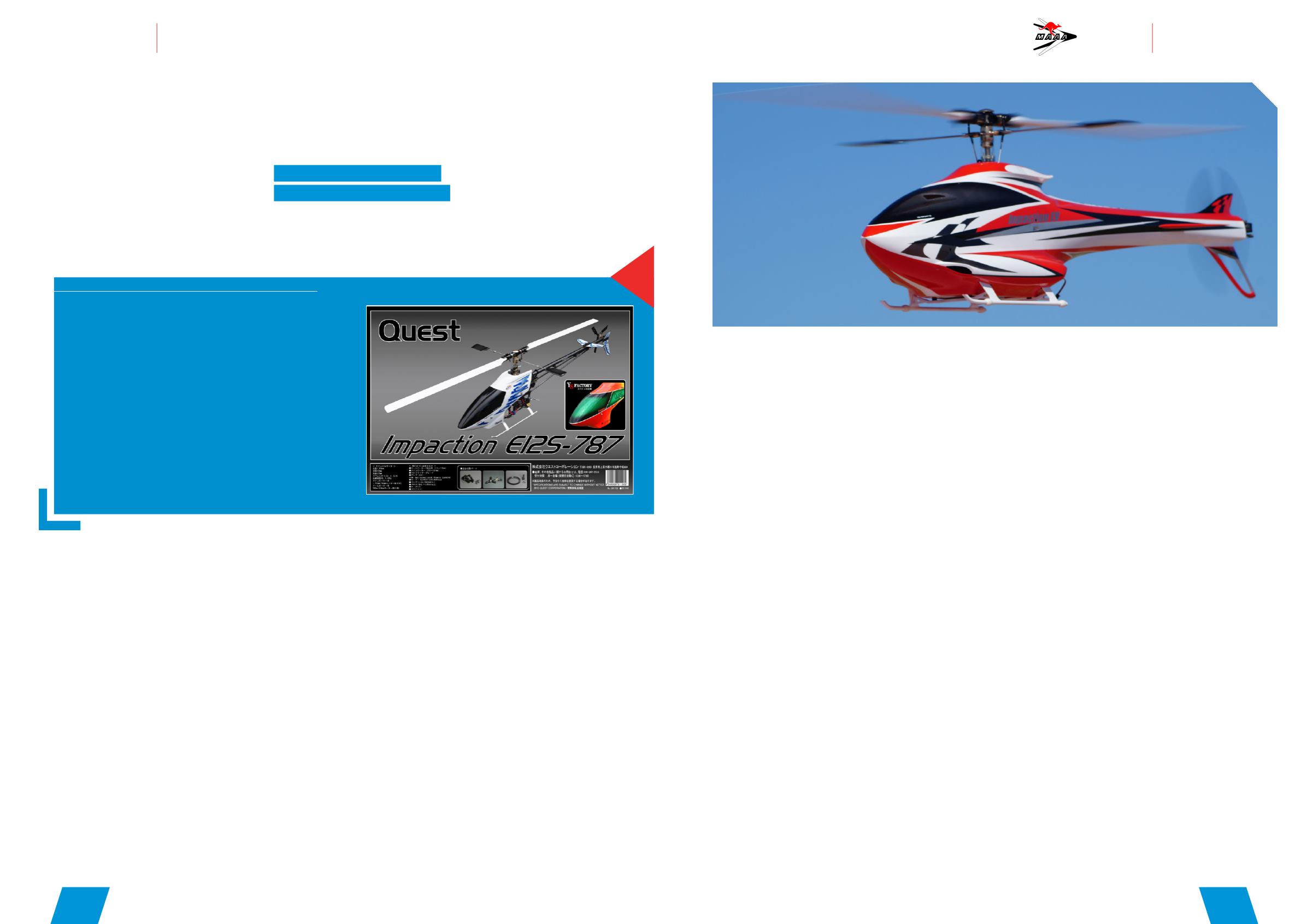
TECHNICAL DATA
Manufacturer: Quest Corporation –
Model: Quest Impaction E12S – 787
Aussie distributor: Countertorque
Length – 1,495mm
Width – 200mm
Overall height – 435mm
Gear ratio – 10.53:1:5.06
Gross weight – About 5,900 g
Main rotor diameter – 1,726 mm (760mm rotor is used)
Tail rotor diameter – 290mm (105mm tail rotor is used)
Battery – 12s 5800mah – 6300mah Lipo batteries
Gear used
Futaba 14MZ transmitter, Futaba CGY
750 3 axis gyro, Futaba BLS272 cyclic
servos x3, Futaba BLS 256HV tail servo,
Scorpion 4530-540kv motor, Castle
Creations Ice 2 HV 160A ESC, Funtech
760mmblades, Funtech 105mm tail
blades, Funtech Staysee 800 fuselage
painted Y’s Factory Japan.
Features
All carbon/aluminium construction
ensuring lightweight and rigidity, two
stage transmission, quick release
battery tray for flight packs.
Overview
In 1999 Kyosho released to the world
the Caliber 60. The design featured
a two stage belt drive transmission,
pull rudder control, and a carbon/
aluminium ladder frame design. It
was the flagship of the range until
Kyosho ended its helicopter line
in 2010. The Kyosho line was then
acquired by Quest Corporation Japan,
which was the original equipment
manufacturer (OEM) for Kyosho,
K&S, Hirobo and other brands. The
company has continued to produce
the Kyosho range of helicopters under
its own brand Quest and continues to
evolve the designs to compete at the
highest levels of competition.
This kit is offered in a variety of
options:
Impaction 787 competition spec
Impaction 787 2 blade FBL (Flybarless)
Impaction 787 3 blade FBL (Flybarless).
The kits are available as a bare kit for
fuselage installation, with a canopy
or even a combo which includes
the Impaction 787 kit and a Funtech
Staysee 800 F3C fuselage.
Thebuild
This helicopter kit is more compact
thanmost, the parts are vacuum
bagged and laid out in order. It
comes with a clear instruction
manual allowing themodeller to
put themachine together quickly
and accurately. A quick look over the
frames (located at the bottomof the
box) and parts and it’s easy to see the
quality of themachining involved.
Step1
I started the build by assembling the frames. The frame
is a stacked frame type whichmeans a top and bottom
frame needed to be assembled. Once each half is built
they needed to be bolted together using spacers and
bolts. Assembly of the top frame was rather simple: first,
I attached the cross members and bearing blocks to the
frame and left the bolts loose. Once all the components
were installed, I placed the frame on a straight bench top
and using a set square tightened each bolt equally. This
ensured the frame was perfectly aligned. The process was
the same for the bottom frame.
Then it was time to join the two frame assemblies together.
Once the bolts and spacers were loosely in position, I
installed themain shaft in the bearing blocks and slowly
tightened each bolt.
Fromexperience I know that it’s important to take time
with this process. While tightening the bolts, I always check
themain shaft is moving up and down in the bearing
blocks freely. If there is any drag on themain shaft it
means the frames are becoming misaligned which will
result in increased drag on the drive train causing poor
performance.
Step2
With the frames assembled, it was time to install the
control arms and servos. The control systemof the
Impaction features a push pull control arm to the swash
plate which provides slop free control and reduced load on
the servo. It does weigh slightly more than a direct servo
setup but the response from this system is more precise.
Step3
The next step was to install the transmission. Themotor is
secured to themotor mount and fitted with the included
pulley. Quest offer a range of pulleys to suit various kv
motors and the instructionmanual provides a chart for you
to select the right pulley for your motor. From themotor,
power to the rotor head is delivered by a ribbed belt to drive
pulley. This drive pulley drives a small helical gear which in
turn drives themain gear installed on themain shaft. The
system is silky smooth and during operation is very quiet.
Step4
Next it was time tomove onto the head. The version on
which I worked is the competition spec so it comes with a
flybar head, but there are also flybarless options available if
you choose to go that way. The head comes pre-assembled
but you can pull it apart and re-grease everything. The
head assembly offers adjustable dampening by turning the
adjustment caps on the end of the yoke but is stuck with
the factory setting.
The tail assembly was quite straight forward but some
gluing was required. The rudder control pushrods required
guides to be glued along the boom to stop the rods from
flapping about whilemaking a control input. I used some 30
epoxy for this task whichmakes it easy to remove the guide
should you break the boom. To finish off the tail it was
simply amatter of bolting together the tail housing, rudder
control arms and sliding the tail hub onto the tail shaft and
tensioning the drive belt and it was ready to go.
One unique feature of the Impaction is the use of a three
bladed tail. This allows the Impaction tomaintain tail
QUEST IMPACTION
e125-787
BROUGHT TO YOU BY MAAA
MEMBER, BRENDAN TUCKER.


